Kirill, the CTO at Subsea Formula, has a broad engineering background and extensive technical knowledge, enabling him to spot unconventional solutions and implement complex technical projects. Today we’re opening Kirill’s project archive—an eclectic mix of robotics, spaceflight training, sensing, energy, and medical engineering. From a three‑metre teleoperated RoboArm showcased alongside Volkswagen and Volvo to a space‑station docking simulator, a multi‑constellation GNSS receiver, an off‑road tracked chair, a flywheel prototype, an automated medical nanofilter plant, and more, here are the ideas, prototypes, and lessons that shaped our work.
- RoboArm
- Mad Chair
- OraculeTang
- Alien Egg
- Flywheel
- GNSS Receiver
- Orbital Docking Trainer
- Medical Nanofilter Plant
- Automated breast tissue-sampling probe device
RoboArm
Overview
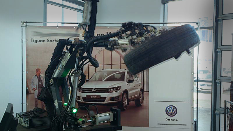
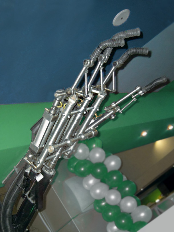
RoboArm is an interactive robotic hand that lets children pilot a giant manipulator via a wearable glove, mirroring finger movements in real time. At three metres long and weighing 350 kg, it was conceived as an exhibition centrepiece inspired by anime mecha. The brief was to deliver smooth, reliable control in public settings and withstand repeated transport and operation. We built a near full‑scale prototype with robust mechanics and noise‑hardened electronics.
RoboArm toured frequently as a reliable showstopper at exhibitions, conferences, and corporate events. Appearances included Volkswagen dealers, Volvo’s heavy machinery division, and pharmaceutical companies’ public and family days. Though designed for children, it consistently engaged adults and technical audiences, sparking inbound interest from nuclear, heavy chemical, underwater, and demining sectors for teleoperation use cases. The project matured into a commercial attraction with repeat bookings and became a foundational prototype for our next‑generation manipulators. The attraction was subsequently acquired by a leading entertainment company.
Technical Solution
- Glove‑based teleoperation mapping finger motion directly to manipulator fingers.
- Dual‑layer noise mitigation combining hardware suppression of relay interference and software filtering of sensor signals.
- Precision TIG welding of high‑strength 40H steel for finger components, using tuned filler selection to prevent cracking on cool‑down.
- Mechanical design validated under high‑frequency loads and occasional off‑nominal use.
- Stable, low‑latency control achieved in electrically noisy exhibition environments.
The main structure used standard structural steel (St3). High‑stress finger elements required 40H steel for strength. Critical joints were TIG‑welded in argon with carefully selected filler rods. Each seam was laid with jeweller‑level precision to manage heat input and residual stress, delivering ductile, crack‑free joints proven in field operation.
The control stack integrated glove input, calibration, mapping, and real‑time filtering tailored to the specific sensor characteristics. Hardware suppression eliminated relay‑induced spikes that could disrupt nearby systems, while software filtration smoothed sensor noise for predictable motion. The result was responsive control suitable for continuous public demos.
Challenges
- Electrical noise from control relays strong enough to reboot adjacent computers, resolved with shielding, suppression, and grounding.
- Sensor noise variability that required case‑specific filtering rather than generic “universal” algorithms.
- Welding 40H steel, overcoming poor weldability through process tuning and filler selection.
- Logistics of transporting and handling a three‑metre, 300–400 kg structure, informing a later shift towards more compact systems.
Lessons learned
- Context beats theory: ostensibly universal filters are not universal in practice.
- Design for mobility early; transport constraints can dominate cost and risk.
- Welding difficult alloys hinges on precise control of filler, heat, and cooling.
- Intuitive interfaces and bounded behaviours are essential for public‑facing robotics.
- Insights from RoboArm led to more compact, transportable manipulators with improved motors and control electronics; however, despite the widely heralded nanotube boom 10–12 years ago, carbon‑fibre ‘muscle’ actuators—especially carbon‑nanotube yarns—have not reached mass use due to unresolved theoretical and practical hurdles, so core teleoperation remains the reliable, repeatable choice.
Mad Chair
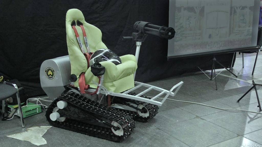
Overview
A full‑functional, battery‑electric tracked chair built for off‑road fun on slopes, sand, and shallow water delivered kart‑like simplicity with go‑anywhere traction. The chair was tested with real users, proved popular, and saw repeat use at shopping centres, private events, off‑road settings, birthdays, and small corporate activations.
Technical Solution
- Battery‑electric propulsion with motors and gearing sized for off‑road starts, gradients, and frequent stop‑start cycles.
- DC motors chosen for strong low‑speed pull and increasing torque with load, paired with current‑aware control to protect the drivetrain.
- Mechanical clutches integrated as torque limiters to safeguard motors and transmissions during jams or sudden track lockups.
- Joystick drive implemented through solid‑state relays and a duty‑cycle (PWM) algorithm on an onboard microcontroller, providing smooth ramping, deadband for stability, and predictable input mapping for beginners.
- Power distribution, fusing, cabling, and connectors specified for high transient currents and comfortable thermal margins during aggressive manoeuvres.
- A tracked undercarriage with tuned geometry, idlers, sprockets, and tensioning for mixed surfaces and tight turns.
- A serviceable chassis and mount system designed for repeated shocks and quick field maintenance, with iterative calibration and shakedown runs across surface types and speed ranges.
Challenges
- Preventing de‑tracking across varied speeds, surfaces, and manoeuvres required precise alignment, optimised sprocket and idler geometry, and consistently maintained track tension.
- Achieving durability demanded fatigue‑resistant mounts and components that resisted cracking and accelerated wear under shock loads.
- Managing high current draw meant controlling voltage sag, connector heating, and SSR thermal dissipation under repeated accelerations and hill climbs.
- Handling jam events called for clutches that slipped cleanly without overheating and control logic that recovered smoothly after load spikes.
- Accommodating unpredictable user behaviour required addressing edge cases children discovered beyond planned scenarios and refining joystick deadband and acceleration limits.
- Staying focused on entertainment avoided scope creep into assistive mobility, which requires separate clinical validation, regulatory pathways, and different ergonomics.
Lessons learned
- Small deviations in track geometry and tension rapidly degrade reliability and raise the risk of de‑tracking, so build tolerances and tension checks are critical.
- Early field testing with children exposes real‑world edge cases that lab planning misses, guiding controller ramps, deadbands, and speed caps.
- Power delivery design is as decisive as motor selection; current limiting, soft‑start ramps, and generous wiring and connectors pay off in responsiveness and uptime.
- Simple, serviceable control units and modular mechanics outperform exotic solutions for public attractions that must run all day and be fixed quickly.
- Mechanical fuses such as clutches are inexpensive insurance for tracks, reducing repair time after stalls and protecting motors and gearsets.
OraculeTang


Overview
OraculeTang is a giant, speaking animatronic orangutan built in eight weeks for Burning Man and engineered to survive the Black Rock Desert’s corrosive, dust‑laden environment while remaining light enough for air transport. The result was a lifelike, cage‑mounted performer with reliable motion, synchronised voice playback, and dependable uptime on the playa.
OraculeTang was installed inside a cage and shown at Burning Man 2015 as part of the Carnival of Mirrors Midway. The piece juxtaposed a lifelike, expressive head with an exposed mechanical frame to underline the tension between nature and machine. OraculTang “spoke” a studio‑produced script divided into four voices—ape, human, robot, and a higher mind—heard by visitors as a fractured dialogue. The cage was deliberately ambiguous, read either as shielding the creature from us or shielding us from it, echoing themes of freedom and constraint.
Technical solution
- Distributed servomotors drove facial and limb mechanisms under a microcontroller, synchronised to audio playback for convincing “speaking” sequences.
- A conditioned DC power system fed a ruggedised amplifier and loudspeakers, with show cues triggered from a simple operator interface.
- A sealed, recirculating air‑cooling loop ducted airflow across electronics and servos to keep dust out while removing heat.
- Quick‑release panels, consolidated harnessing, and clearly labelled subsystems enabled fast field swaps during show windows.
Challenges
- Protecting mechanisms and electronics from pervasive alkaline dust required a single, fully recirculating, shared cooling loop and a sealing strategy that still allowed maintenance access. Black Rock’s micron‑scale alkaline dust was countered by maintaining positive internal pressure and selecting dust‑tolerant connectors, bearings and seals.
- Heat from motors and the audio system was modelled for high ambient temperatures, and airflow was sized to derated components to protect performance over long daily runs.
- Strict air‑freight limits set a hard mass budget for the figure, cage, and ancillaries, so aluminium members were used wherever stiffness‑to‑weight mattered most, with steel reserved for attachment points, wear surfaces, and rigging hardware. Major assemblies were modularised to fit crate dimensions, speed load‑in and load‑out, and simplify venue‑to‑venue handling. Balancing low weight with durability drove a mixed aluminium–steel structure and attentive fastener and interface design to mitigate galvanic risk.
- Meeting the compressed schedule demanded parallel workstreams in sculpting, mechanisms, controls, audio, and crating, with frequent integration checkpoints.
Alien Egg
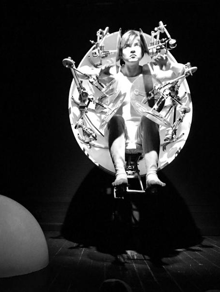
Alien Egg was a lightweight, flyable stage prop: a gleaming ovoid that opened to reveal a performer, built on a steel skeleton with a fiberglass shell, aluminium manipulators, and plastic mirrors. A concealed hydraulic system lifted the egg slightly at each show opening, integrated with standard show‑control cues and a rated flying setup featuring defined attachment points, redundant restraints, quick‑release ground access, and clear egress procedures. Inside, an illuminated array of adjustable mirrors on compact manipulators produced shifting, kaleidoscopic reflections; the performer could move the arms smoothly by hand and leave them parked in space, achieved with compact, custom, adjustable clutches on the manipulators’ revolute joints (with motorised assistance where required). The result was a high‑stiffness, low‑mass construction that met aerial rigging limits, delivered a safe, repeatable reveal, and enabled fast resets with consistent sight‑lines across venues.
Flywheel
Overview
A compact flywheel energy storage prototype was built to explore practical limits with available materials, bearings, and power electronics, proving the principle on a palm‑sized device that could spin up and return short bursts of energy. The prototype was exhibited at the Archimedes innovation fair and received a gold medal from the jury. Further development was paused owing to the need for significant investment and a clear application pathway, as well as shifting political conditions in the former country of residence.
Technical Solution
- A small high‑speed rotor and enclosure demonstrated kinetic energy storage with electrical spin‑up and recovery.
- Simple power electronics enabled controlled charge and discharge cycles for brief, repeatable output.
- The build focused on validating stability, losses, and safe operation at speed rather than maximising stored energy.
- Component choices prioritised manufacturability with then‑available processes to assess a realistic scaling path.
Challenges
- Scaling required high‑strength rotors, precision machining, low‑loss bearings or magnetic levitation, and vacuum housings to control drag and heat.
- Safety containment for high‑RPM failure modes and compliant power electronics added complexity and cost.
Lessons learned
- The principle works at small scale, but practical systems demand advanced materials, bearings, vacuum containment, and rigorous safety engineering.
- Early definition of use cases and commercial endpoints is essential before committing to deep‑tech scaling.
- External context matters, as policy and geopolitical shifts can halt otherwise promising R&D programmes.
- In the team’s view, hydrogen and fuel cells merit attention for long‑duration storage, while flywheels best suit short, high‑power buffering where fast cycling and long life are valued.
GNSS Receiver
Overview
A multi‑channel, multi‑constellation GNSS receiver developed from first principles, covering GPS, GLONASS, Galileo, and BeiDou, with a host‑side test interface that exposed live channel status, signal quality, and decoding diagnostics. The work spanned the full flow from early bench prototypes to a custom baseband processor in hardware, providing hands‑on experience of how software signal processing is progressively migrated into silicon for performance and power. Unfortunately, project artefacts were lightly photographed at the time, limiting archival media despite successful bring‑up.
Technical Solution
- Custom baseband processor designed, simulated, and implemented to handle parallel acquisition and tracking, code/carrier loops, and navigation data decoding.
- RF front‑end and clocking chain selected for low noise and stability, feeding correlators optimised for multi‑constellation, multi‑frequency operation.
- Host computer application provided a visual test interface for clients, showing satellite visibility, lock state, C/N0, PRNs, ephemerides, and health metrics.
- Hardware evolution moved from a mock‑up board with off‑the‑shelf processors to an integrated receiver with tailored digital logic and refined power distribution.
- Lab bring‑up and debugging relied on practical instrumentation (oscilloscope, multimeter) plus careful documentation, enabling rapid iteration without hard‑to‑source equipment.
Challenges
- RF integrity demanded meticulous layout, grounding, and isolation to prevent self‑interference and cross‑talk between high‑gain paths and digital logic.
- Power integrity under simultaneous multi‑channel operation required robust decoupling, rail stability, and transient tolerance.
- Partitioning algorithms between firmware and hardware needed repeated profiling to balance silicon area, throughput, and flexibility.
- Integration exposed edge‑case timing and component‑tolerance issues that necessitated board reworks and loop retuning.
- Usability for engineering clients called for a clear UI vocabulary and live observability to shorten diagnosis and acceptance testing.
Lessons learned
- Design for test from day one: expose internal signals, log loop states, and build tooling that shortens root‑cause analysis.
- Prove it in software, then harden in hardware: migrate the hottest paths first while retaining firmware hooks for updates.
- Treat RF, clocking, and power as one system; small PCB and grounding changes can unlock outsized performance gains.
- Simple, dependable lab practice and thorough documentation often beat hard‑to‑source equipment.
Orbital Docking Trainer
Overview
A space station and spacecraft docking simulator developed for the Gagarin Cosmonaut Training Center, combining a real‑time dynamics model, 3D visual scene, and virtual instruments with a human centrifuge to reproduce g‑loads during approach and contact. The system allowed manual piloting with inputs mapped to translational and rotational thrusters, mirroring operational training conventions for space rendezvous. A functioning prototype supported trials and informed a Kirill’s graduation thesis before being handed over for to the next cohort for continuation. The project was accompanied by ten boxes of printed documentation.
Technical Solution
- A mathematical model of relative motion and reaction control thrustering drove real‑time guidance, navigation, and control loops.
- A 3D visualisation and virtual dashboard presented approach geometry, rates, and attitude cues aligned to cosmonaut training conventions.
- A human‑in‑the‑loop interface allowed manual piloting with input devices mapped to translational and rotational jets.
- The simulator synchronised with the centrifuge control loop to command g‑profiles consistent with the docking manoeuvre timeline.
- A multi‑computer setup typical of the period combined a VAX‑class host and UNIX‑based workstations with multiple I/O racks for real‑time interfacing.
Challenges
- Maintaining deterministic real‑time performance under rendering, control, and I/O load without inducing latency spikes.
- Keeping the physics model numerically stable near contact where small errors amplify pilot workload.
- Matching display symbology and behaviour to established cosmonaut training standards for rapid skill transfer.
- Achieving reliable, low‑jitter synchronisation between the simulator host and centrifuge controllers.
- Managing hardware fragility across several electronics racks and ensuring recoverable failure modes during sessions.
- Preserving continuity and knowledge transfer as student engineers graduated and new team members arrived.
Lessons learned
- Build to real‑time constraints first, then add visual fidelity once control latency budgets are met.
- Co‑simulate actuators and plant dynamics to avoid surprises at low‑rate, high‑precision final approach.
- Prioritise human‑factors fidelity so trained procedures carry over to flight hardware and mission timelines.
- Enforce robust documentation and handover practices to survive cohort turnover in long‑running training systems.
Medical Nanofilter Plant
Overview
A fully automated factory was designed to produce low‑cost respiratory filters for mechanical ventilation and ICU use, with targets of preserving inhaled humidity, blocking airborne microorganisms, and partially scrubbing carbon dioxide to raise the effective oxygen fraction for vulnerable patients. The concept emphasised a manufacturable membrane made from a specific, under‑used material and an assembly flow that kept unit costs down for wide clinical deployment. Elements of the approach received independent positive assessments in a naval medical setting for lung‑injury cases, but the programme was paused owing to ethical concerns about funding in the former country of residence.
Technical Solution
- An end‑to‑end automated line was specified, from polymer feedstock through nano‑scale fibre formation to membrane lay‑up, cartridge assembly, and sealed packaging.
- The filter architecture was defined to retain moisture in the breathing circuit, capture bacteria and other microorganisms, and target partial CO₂ removal while maintaining low breathing resistance.
- The process plan prioritised simple, repeatable steps and commodity components to achieve affordable unit economics and scalable output once commissioned.
- Tooling, fixtures, and control logic were kept modular so stations could be validated independently and integrated as throughput demands increased.
Challenges
- Selecting the membrane material was the hardest problem, requiring trade‑offs across permeability, capture efficiency, moisture retention, and stability; a promising but overlooked candidate was identified after extensive review.
- Building even a first article depended on non‑off‑the‑shelf nanofibre spinning equipment, creating a high upfront threshold before meaningful prototyping could begin.
- Reconciling contradictory goals—humidification, antimicrobial capture, and CO₂ scrubbing—demanded tight control of fibre diameter, pore distribution, and surface chemistry.
Lessons learned
- Solve the material science first; once the membrane works, automation, factory layout, and per‑unit cost targets become straightforward.
- Plan for prototype‑enabling equipment early, including access to nanofibre formation machinery and test rigs, to avoid programme stalls.
- Design the production flow for low part count, short cycle times, and simple quality checks to keep costs down without compromising safety.
- Secure clean governance and financing pathways from the outset; ethical and regulatory readiness are as critical as technical feasibility.
Automated breast tissue-sampling probe device
A clinic‑commissioned design for an automated, mammography‑guided sampling probe that standardises breast tissue collection for consistent, reproducible results even in non‑specialist hands. The project delivered the full device architecture and a simple operator test interface; the design was handed over to the client.