UXO Survey USV and Magnetometer Kits
UXO survey systems for offshore wind. Magnetometer kits, G-882 TVG gradiometer payload kits and a full unmanned surface vessel system on Sula 8.
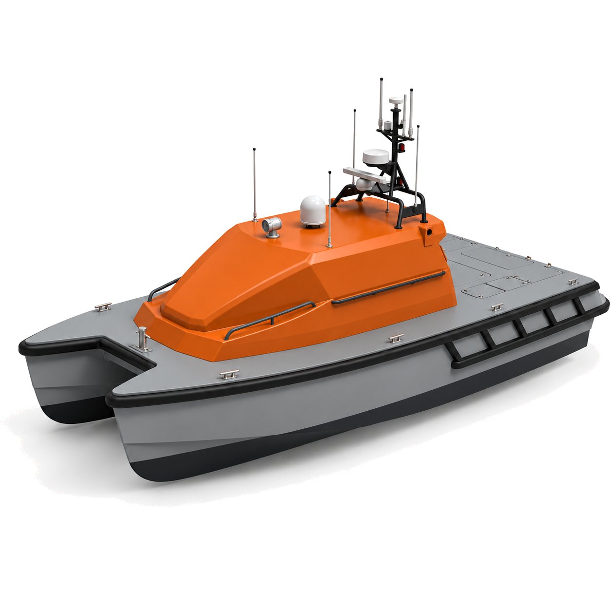
We supply magnetometer kits, UXO payload kits and complete unmanned surface vessel (USV) systems for pre-construction UXO survey in offshore wind. The full system runs on Sula 8, our offshore platform. Each kit is configured for your vessel and survey, then commissioned and handed over to your team. You, the survey contractor or developer, hold the certification and run the survey. We don’t operate surveys.
Survey deliverables, method and regulation
The deliverable is a target list. Each contact carries a position, an estimated burial depth and a magnetic dipole, and the project’s UXO consultant reviews the list. Contacts are then re-acquired by ROV or diver, so the position you hand over sets the size of the search circle around every target.
The established method is a crewed vessel towing an ROTV with a magnetometer gradiometer array, with side-scan and multibeam alongside. The EIVA ScanFish Katria carrying four Geometrics G-882 is the incumbent array. The shift is to USVs towing the same sensors, and a USV has already towed a G-882 on a commercial offshore-wind UXO survey.
In the Netherlands, UXO survey is built into offshore-wind permitting and offshore detection work requires CS-OOO certification. German permitting embeds UXO desk studies in the same way. The kits are for survey contractors and developers working the North Sea and the Baltic.
Configuration requirements
Three numbers decide most of the configuration. Take them from your threat assessment and your UXO consultant’s definition of the smallest target, then check the configuration against them.
Detection range, sensor altitude and line spacing
A magnetometer detects an item out to a distance that depends on the item’s size. Published estimates of maximum detection distance (SPH Engineering):
| Item | Maximum detection distance |
|---|---|
| 81 mm shell | About 1 m |
| 105 mm shell | About 4 m |
| 215 mm shell | About 5 m |
| 500 lb bomb | More than 7 m |
Grenades and 20 mm rounds need a standoff below 1 m. The detection distance is roughly the sensor altitude plus the burial depth of the item.
- Line spacing must not exceed twice the detection range of the smallest target. For shell-class targets that gives 1 to 2 m. For large bombs only, spacing can open to about 6 m. At a 3 to 4 m tow, an 81 mm shell (about 1 m) is outside what a towed array finds, and a 105 mm shell (about 4 m) is at the edge. The 1 to 2 m spacing is what shell-class targets need, and reaching them takes a lower tow altitude.
- Sensor altitude on a towed array is 3 to 4 m. German guidance caps it at 4 m for 250 lb bombs and 6 m for 500 lb bombs.
- Where the smallest target’s detection range is shorter than the tow altitude, a towed array will not find it. Settle that against the consultant’s target definition before you choose the configuration.
Track-keeping
At 2 m line spacing the track has to hold within ±0.5 to 1 m across the line. The USV flies planned survey lines, with RTK GNSS position and dual-antenna heading as standard. Autopilot integration is available.
Towed-sensor positioning
Re-acquisition is usually planned against IHO S-44 Special Order, 2 m total horizontal uncertainty at 95%. Your contract may set a different figure. Under 2 m is typical for reliable relocation, and about 5 m is a practical edge, where the ROV search circle grows. Magnetic localisation by dipole inversion typically adds about 0.5 to 2 m on top of the vehicle position.
A towed sensor sits astern of the vessel and below it. We position it two ways:
- USBL. A Blueprint Subsea SeaTrac X150 head on the hull tracks an X010 beacon on the gradiometer frame. Sonardyne Micro-Ranger 2 is the other option.
- Layback. Cable-out from the winch’s cable counter, with the sensor’s depth and altimeter readings, gives a computed position. It is the cross-check on the USBL, and the fallback when the USBL drops out.
Sensor configuration
Magnetometers
| Class | Sensors | What matters for UXO |
|---|---|---|
| Caesium, optically pumped | Geometrics G-882; G-882 TVG | The standard UXO sensor. Noise below 0.004 nT/√Hz. Each G-882 fish weighs 18 kg and draws 12 to 16 W. The TVG carries two fish on a frame with 1.5 m sensor separation, about 150 lb for the frame, with 400 ft of cable. |
| Overhauser | Marine Magnetics SeaSPY2, Explorer; SeaQuest2 towed gradiometer | SeaQuest2 carries four sensors at 1.5 m transverse spacing. |
| Fluxgate | SENSYS MX3D array | Vector sensors in an array. |
We configure the payload kit and the full system around the G-882 TVG. It is the sensor in the crewed-vessel arrays that UXO surveys have been accepted on, and in the USV-towed surveys. The other classes are configurable where a project specifies them.
Why a gradiometer. Two or more sensors at a fixed spacing, with a baseline of about 1.5 m, suppress the background from seabed geology. A gradiometer is best practice for UXO survey. The geometry between the sensors is fixed by the rigid frame, so it does not depend on navigation.
Sub-bottom profiler and side-scan
The magnetometer finds ferrous items, buried or not. It does not see anything else, so two acoustic sensors cover the rest:
- Parametric sub-bottom profiler. The Innomar SES-2000 images buried objects. The compact version has a transducer of about 22 kg on 20 m of cable, a topside of about 15 kg, and draws 50 W typical and 100 W at most. It needs a survey INS for heave, roll and pitch. One modelling study puts about 22% of items on the surface, 54% in the top 0.5 m and 6% below 1 m.
- Towed side-scan. The EdgeTech 4205 is the survey standard. A JW Fishers 450/900 kHz CHIRP towfish on a reel and depressor is the alternative, and its 900 kHz channel gives the small-target resolution. The depressor is non-ferrous.
Platform magnetic noise
The hull has its own magnetic signature, and seabed geology adds background on top. We handle the hull's signature three ways:
- The magnetometer tow rides furthest astern, clear of the side-scan line.
- Tow length is set from a measured vessel signature and heading test on your hull. A rule of thumb would hide it.
- Sensor timing across the magnetometer, side-scan and sub-bottom profiler is aligned during calibration.
Acquisition and processing
One survey GNSS/INS is the reference for every sensor. It supplies RTK position, heading, and heave, roll and pitch to the sub-bottom profiler and the acquisition software, with PPS time sync to each sensor.
| Step | Software |
|---|---|
| Line planning, logging of the acoustic sensors and online QC | EIVA NaviSuite Kuda |
| Side-scan processing | EIVA NaviSuite Processing |
| Magnetic processing, dipole modelling and target picking | Seequent Oasis montaj with UX-Detect |
The data chain runs from the sensors into one survey computer, then through EIVA for logging of the acoustic sensors and side-scan and Oasis montaj UX-Detect for the magnetic data. UX-Detect produces the target list your UXO consultant reviews. We configure the chain from raw data to target list for your survey.
Supply options
There are three levels, each configured to order.
1. Magnetometer kit
For your vessel or USV:
- a towed total-field marine magnetometer, with an altimeter where the configuration needs one;
- a tow cable and reel;
- integration with your vessel’s positioning, so every reading is logged with a position.
It suits a contractor adding magnetic survey to a vessel it already runs. The towed sensor’s position comes from tow geometry. Industry practice for UXO survey is a gradiometer, which the payload kit provides.
2. UXO payload kit for your own USV or vessel
- a G-882 TVG gradiometer on its frame, with tow cable;
- a tow winch with a cable counter and slip ring;
- SeaTrac USBL positioning of the towed frame, with layback as the cross-check;
- EIVA NaviSuite Kuda and Processing and Oasis montaj UX-Detect on a survey computer, configured as the chain from raw data to target list.
The kit uses the survey GNSS/INS on your vessel. A survey GNSS/INS is available as an option.
Check your hull against what the kit asks of it. It needs a tow point and recovery gear for the frame and its winch, a power supply for the sensors, and a magnetic signature you can measure and tow clear of.
3. Full UXO survey system on Sula 8
- Sula 8, configured with two tows. One carries the G-882 TVG gradiometer, and the other carries a side-scan towfish with reel and depressor.
- A parametric sub-bottom profiler such as the Innomar SES-2000, with a survey-grade INS.
- USBL tracking of the towed bodies and a powered winch.
- RTK GNSS position with dual-antenna heading, communications by radio link, coastal 4G and 5G, and satellite.
The Sula 8 page has the platform specification and the UXO payload list. For a single magnetometer tow in near-shore water, Sula 5 is the smallest platform we configure for a G-882 tow. Options on the full system include a survey multibeam. Where the survey runs close to existing structures and GNSS can drop out, add our GNSS-denied navigation.
Integration and support
- Configure the kit for your vessel. Tow points, winch and reel, wiring and acquisition software are set for one hull.
- Calibrate on the vessel. We measure its magnetic signature, set the tow length so the sensors sit outside it, check the positioning of the towed frame and align sensor timing.
- Commission the kit with a sea acceptance run.
- Train your operators in tow operations, acquisition and quality control, and magnetic processing to a target list.
Every kit comes with commissioning on your water, operator training, and support from our UK and EU teams.
Each kit is configured to order and quoted per boat. Tell us your vessel or USV, the survey area and the smallest targets you need to find, and we’ll configure a kit for it.
Limitations
- The magnetometer responds only to ferrous material. Other objects need side-scan on the seabed and the sub-bottom profiler below it.
- At a 3 to 4 m tow, an 81 mm shell (detection range about 1 m) is outside what a towed array finds, and a 105 mm shell (about 4 m) is at the edge. Grenades and 20 mm rounds, which need a standoff below 1 m, are outside it too. A 215 mm shell (about 5 m) and a 500 lb bomb (more than 7 m) are within it. Shell-class spacing of 1 to 2 m needs a lower tow altitude.
- On the magnetometer kit, the towed sensor’s position is estimated from tow geometry. For contacts you need to re-acquire, the payload kit adds USBL positioning of the frame.
- A survey produces contacts. Identifying a contact takes a follow-up inspection, and removing it is separate work.
- Each configuration is set up for one hull, with its own tow points, cable lengths and calibration.
Questions and answers
What line spacing and sensor altitude does a USV UXO survey need?
Line spacing is no more than twice the detection range of the smallest target: 1 to 2 m for shell-class targets, up to about 6 m for large bombs only. A towed array flies 3 to 4 m above the seabed. At that altitude an 81 mm shell (about 1 m) is outside what the array finds and a 105 mm shell (about 4 m) is at the edge, so shell-class spacing needs a lower altitude. At 2 m spacing the track has to hold within ±0.5 to 1 m.
What positioning accuracy does re-acquisition need?
It is usually planned against IHO S-44 Special Order, 2 m horizontal uncertainty at 95%, though your contract may set another figure. Under 2 m is typical for reliable relocation. At about 5 m the ROV search circle grows. Dipole inversion typically adds about 0.5 to 2 m on top of the vehicle position.
Which magnetometer do you configure for UXO?
The Geometrics G-882 in a TVG gradiometer, the sensor used in the crewed-vessel arrays and in USV-towed offshore-wind UXO surveys. Marine Magnetics SeaSPY2, Explorer and SeaQuest2, and the SENSYS MX3D, are configurable where a project specifies them.
Why use a gradiometer for UXO survey?
A gradiometer holds two or more magnetometers at a fixed spacing, about 1.5 m, which suppresses background from the seabed geology. It is best practice for UXO survey.
How is the target list produced?
EIVA NaviSuite logs the acoustic sensors with online QC. Seequent Oasis montaj with UX-Detect processes the magnetic data and produces the target list, with position, burial depth and dipole for each contact.
Can I fit the UXO payload kit to a USV or vessel I already own?
Yes. We check your hull’s tow points, power, space and magnetic signature, configure the payload kit for it, calibrate on your vessel and commission the kit on your water.
Do you run UXO surveys?
No. We supply and support the kit. The survey contractor or developer holds the certification its market requires, such as CS-OOO in the Netherlands, and runs the survey.
Will my client’s UXO consultant accept the data?
Acceptance is settled between you, your client and the project’s UXO consultant. The payload kit uses a G-882 gradiometer, the sensor in the arrays UXO surveys have run on, and we train your team in the workflow to a target list.
Discuss a UXO Survey Kit
Tell us your vessel or USV, the survey area and the targets you need to find.
